Teacher Portal:
Simple Machines
Investigation 2 – Lab

ZERO-IN
Italicized font represents information to be shared orally or physically completed with the students at this time.
The non-italicized font represents additional information included to support the teacher’s understanding of the content being introduced within the CELL.
MINDSET
This Investigation is designed to:
- illustrate to students that work is force applied over a distance,
- allow students to discover that a simple machine makes work seem easier by changing the direction in which the effort force is applied,
- demonstrate to students that mechanical advantage is the ratio of load force to effort force,
- illustrate to students that mechanical advantage can also be measured as the ratio of effort arm length to load arm length,
BE PREPARED
Teacher Preparation for the Investigation includes the following. This preparation should be done prior to students arriving in the lab.
- Place all materials at the distribution center.
- Divide students into five cooperative groups.
Note: Each student lab group will need the materials listed below.
Student Preparation for the Investigation includes having students gather the following materials. This preparation takes place on lab day after student lab groups have settled at their assigned lab tables.
Note: The materials are listed in students’ SDRs. They are also listed below for your reference.
- 1 prism
- 3 metric rulers
- 1 wooden block
- 2 100 gram masses
- 1 calculator
- 1 roll of masking tape
- 1 spring scale
- 1 stick of clay
Direct one student from each lab group to collect the materials listed in their SDRs.
INVESTIGATE
- Encourage students to reflect on the PreLab video as they move through the procedural steps.
- Explain to students that during the Experiment, every procedural step is important. If one step is skipped, data can become invalid. To help students keep on track, direct them to read each step thoroughly, complete the step, then check it off (Read it – Do it – Check it off).
- Direct students to complete the procedural steps in their SDRs.
Note: The procedural steps are listed below for your reference. Teacher “Notes” are inserted, as needed, to help facilitate the lab.
Trials 1-4:
- In these Trials, you will investigate how changing the position of the load on a first-class lever affects the effort force required to lift the load.
- How will moving the fulcrum of a first-class lever closer to the load affect the effort force needed to lift the load? Student answers will vary.
- Determine the force of gravity on the load that will be used in the experiment. This is the load force.
A. Two 100 gram masses will be used as the load for the experiment. The masses that will be used are calibrated. Therefore, they do not need to be placed on a triple beam balance to determine their mass.
B. Calculate: Use the following formula to determine the force of gravity on the load. Remember to convert grams to kilograms. Round the answer to the nearest whole number.
Force of gravity (N) = mass (kg) x g g = 9.8 m/s2
Force = 0.2 kg x 9.8 m/s2
Force= 1.96 N
Force= 2 N
C. Record: Write the load force in each row of the column labeled “Load force” in Tables A and B on the last page of the Student Data Record.
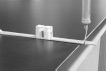
4. Construct a first-class lever using the following steps: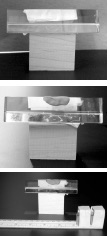
A. Attach a wooden block to the prism using a piece of masking tape. This will be the fulcrum of the lever.
B. Place a small amount of clay over the fulcrum to help steady the ruler.
C. Attach two 100 gram masses to the 30 cm end of a metric ruler with two pieces of masking tape. This is the load.
D. Calibrate the spring scale. Hold it by the handle and move the adjustment nut until the indicator platform aligns with the “0” mark.
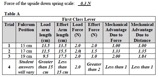
E. Record: Measure the force of gravity on the spring scale. Hold it upside down by the hook. Observe the force. Record the Record the force above Table A.
F. Calibrate the spring scale for use in an upside down position. Hold it by the metal hook. Turn the adjustment nut until the platform is even with the “0 N” mark on the Newton scale.
G. Hang the spring scale on the side of the ruler by 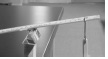 placing the hook into the hole located at the 1.5 cm mark. If the ruler does not have a hole, use tape to secure the hook to the ruler at the 1.5 cm mark. This end of the ruler is the effort arm.
H. Place the lever system so that the end with the spring scale is off the table.
Trial 1:
- Position the ruler so that the fulcrum is located at the 15 cm mark between the load and effort.
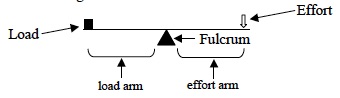
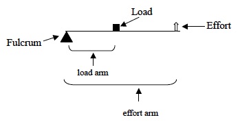
- Determine the length of the load and effort arms.
A. Length of load arm = Distance from fulcrum to center of load. The center of the load is the point between the two 100 g masses.
B. Length of effort arm = Distance from the fulcrum to the center of the effort.
C. Record. Measure the length of the load arm and record the length in Table A.
D. Record. Measure the length of the effort arm and record the length in Table A.
- Pull down on the spring scale until the ruler is
 completely horizontal.
 - Record: Look at the spring scale. Measure the force applied to the ruler when the ruler is completely horizontal. Read the amount of force applied to the ruler and add to it the force of the upside-down spring scale recorded above Table A. Write the sum in the column of Table A labeled “Effort Force (N)”. This is the effort force.
Trial 2:
- Move the fulcrum to the 17 cm mark.
- Repeat the procedures used in Trial 1 to measure the length of the effort arm, the length of the load arm, and the effort force.
Trial 3:
- Move the fulcrum to the 19 cm mark.
- Repeat procedures used in Trial 1 to measure the length of the effort arm, the length of the load arm, and the effort force.
Note: The Analysis Questions for Trials 1-3 are located on the PostLab page for Investigation 2.
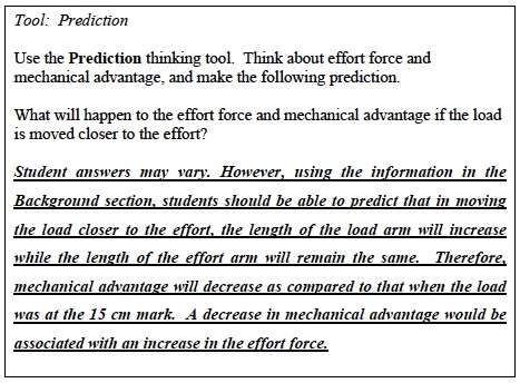
- Predict what the effort force and mechanical advantage would be if the fulcrum were moved between the 0 cm and 15 cm mark on the ruler. Students should suggest that moving the fulcrum closer to the effort would decrease the length of the effort arm and therefore increase the effort force over that of the load force. As a result, mechanical advantage would be less the mechanical advantage when the effort force and load force are equal, i.e. less than 1.
Trial 4:
- Test the prediction. Move the fulcrum anywhere between the 0 cm and 15 cm mark on the ruler.
A. Record: Write the position of the fulcrum in Table A.
B. Record: Measure the length of the load arm and record the length in Table A.
C. Record: Measure the length of the effort arm and record the length in Table A.
D. Pull down on the spring scale until the ruler is completely horizontal.
E. Record: Look at the spring scale. Read the amount of force applied to the ruler and add to it the force of the upside-down spring scale recorded above Table A. Write the sum in the column of Table A labeled “Effort Force (N)”.
F. Calculate: Determine the mechanical advantage due to force and distance and record the results in Table A.
G. Compare the effort required to lift the load in this trial to Trial 1, 2, and 3. Did it feel easier or harder to lift the load in this trial? Why? It felt harder to lift the load in this trial as compared to Trials 1, 2, and 3 because the effort force was greater than the load force. The effort force increased because the length of the effort arm decreased and the length of the load arm increased.
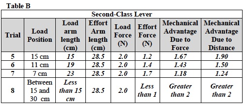
Trials 5-8:
- In these trials, you will investigate how changing the position of the load on a second class lever affects the effort force required to lift the load.
- Begin to build a second class lever. Remove the prism and the wood block from the first-class lever assembly.
- Re-calibrate the spring scale for use in the normal upright position by holding the spring scale by the metal loop. Turn the adjustment nut until the platform is even with the “0 N” mark on the Newton scale.Refer to the Spring Scale (5N) Use and Operation procedure for assistance if necessary.
- Construct a second-class lever as follows:
A. Remove the masses and masking tape from the end of the ruler.
B. Attach the two 100 gram masses to the ruler so that the two masses are touching each other at the 15 cm mark. This is the load.
C. The force of this load is 2 N, as measured in the first part of the experiment. This is already recorded in Table B in the Student Data Sheet.
Trial 5:
- Construct the effort arm. Connect the spring scale to
 the ruler by placing the hook end through the hole of the ruler at the 1.5 cm mark. If the ruler does not have a hole, use tape to secure the hook to the ruler at the 1.5 cm mark. This is the effort arm.
 - Find the length of the load and effort arms.
A. Length of load arm = Distance from fulcrum to center of load.
B. Length of effort arm = Distance from the fulcrum to the center of the effort.
C. Record: Measure the length of the load arm and record the length in Table B.
D. Record: Measure the length of the effort arm and record the length in Table B.
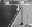
- Find the effort force required to lift the load 5 cm off the table.
A. Place the lever system so that the 4 cm mark is even with the table.
B. Hold the fulcrum end of the ruler against the 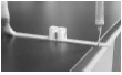 table with the tips of your fingers. Use enough force to prevent the ruler from sliding when the effort force is applied.
C. Pull up on the spring scale until the spring scale is vertical. The platform should be at “0”.
D. Hold a metric ruler vertically beside the load. Pull up on the spring scale to lift the load until the edge of the lever is at the 5 cm mark.
E. Measure the force applied on the ruler. This is the effort force. Record in Table B.
Trial 6:
- Move the load to the 11 cm mark.
- Repeat the procedures from Trial 5 to measure the length of the effort arm, the length of the load arm, and the effort force.
- Record your results in Table B.
- Compare the effort required to lift the load in this trial to Trial 5. Did it feel easier or harder to lift the load in this trial? It felt harder to lift the load in this trial as compared to Trial 1.
Trial 7:
- Move the load to the 7 cm mark.
- Repeat the procedures from Trial 5 to measure the length of the effort arm, the length of the load arm and the effort force.
- Record your results in Table B.
- Compare the effort required to lift the load is this trial to Trials 5 and 6. Did it feel easier or harder to lift the load in this trial? It felt harder to lift the load in this trial as compared to Trials 5 and 6.
Trial 8:
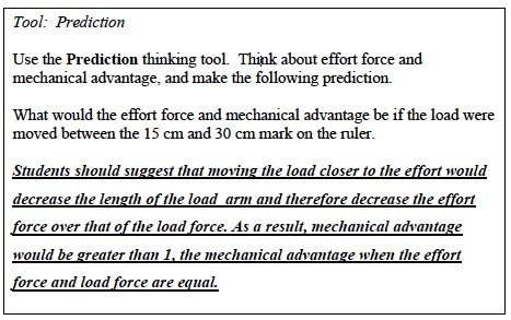
- Test the prediction. Move the load anywhere between the 15 cm and 30 cm mark on the ruler.
A. Where will the load be positioned? Student answers will vary.
B. Repeat the steps used in Trial 5 to determine the effort force needed to raise the load 5 cm off the table. Write the effort force in Table B.
Note: The Analysis Questions for Trials 5-8 are located on the PostLab page for Investigation 2.
CLEAN UP
Let students know your expectations for clean up. Ask them to clean up.