Teacher Portal:
Electricity and Magnetism
Investigation 2 – Lab

ZERO-IN
Italicized font represents information to be shared orally or physically completed with the students at this time.
The non-italicized font represents additional information included supporting the teacher’s understanding of the content being introduced within the CELL.
MINDSET
This Investigation is designed to:
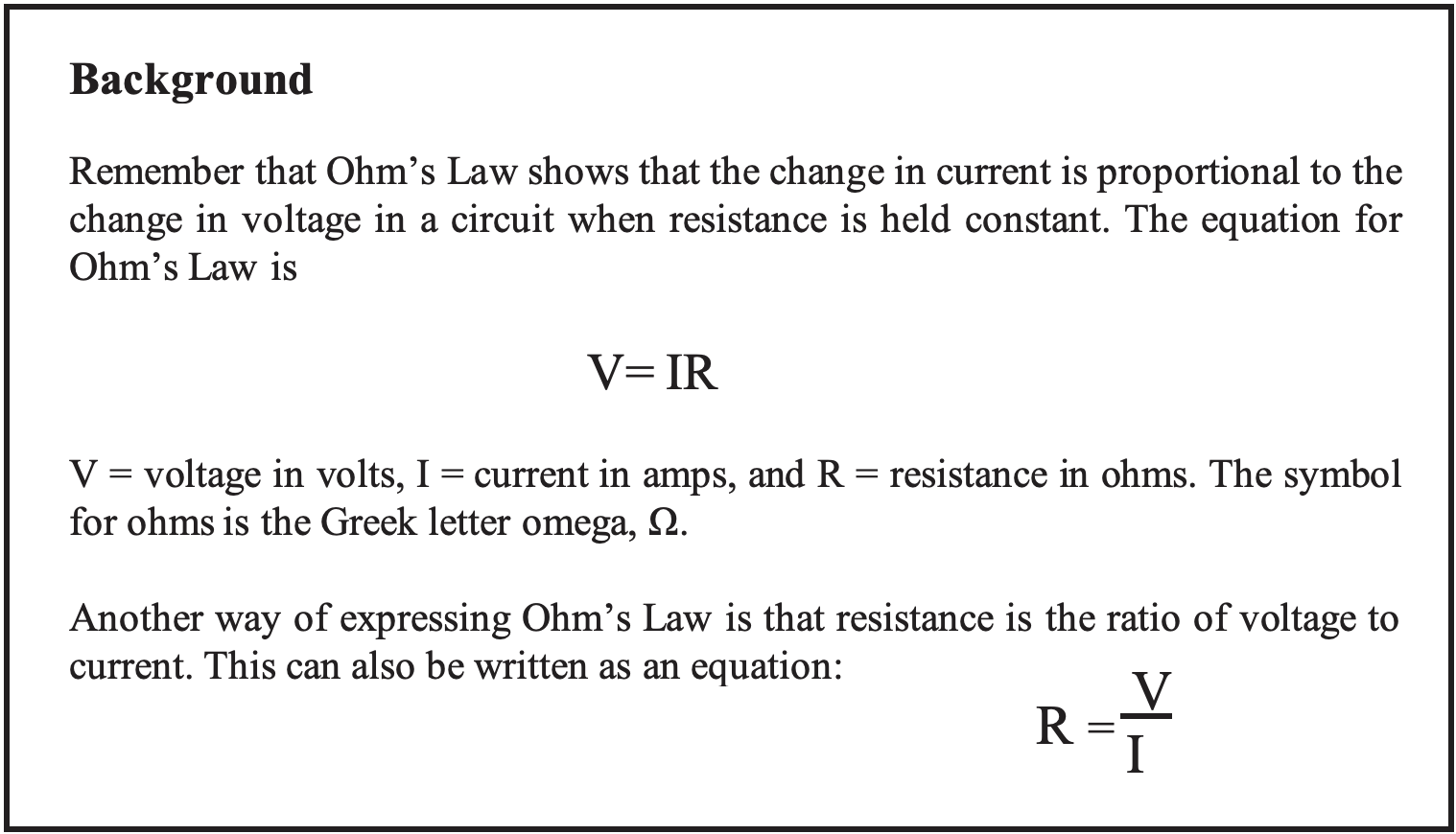
- reinforce for students that the amount of current in a circuit is proportional to the amount of voltage supplied by the power source,
- allow students to discover that the ratio of voltage to current changes when voltage is held constant but resistance changes,
- reinforce that the ratio of voltage to current is resistance,
- reinforce that the relationship between voltage, current, and resistance is captured by Ohm’s Law,
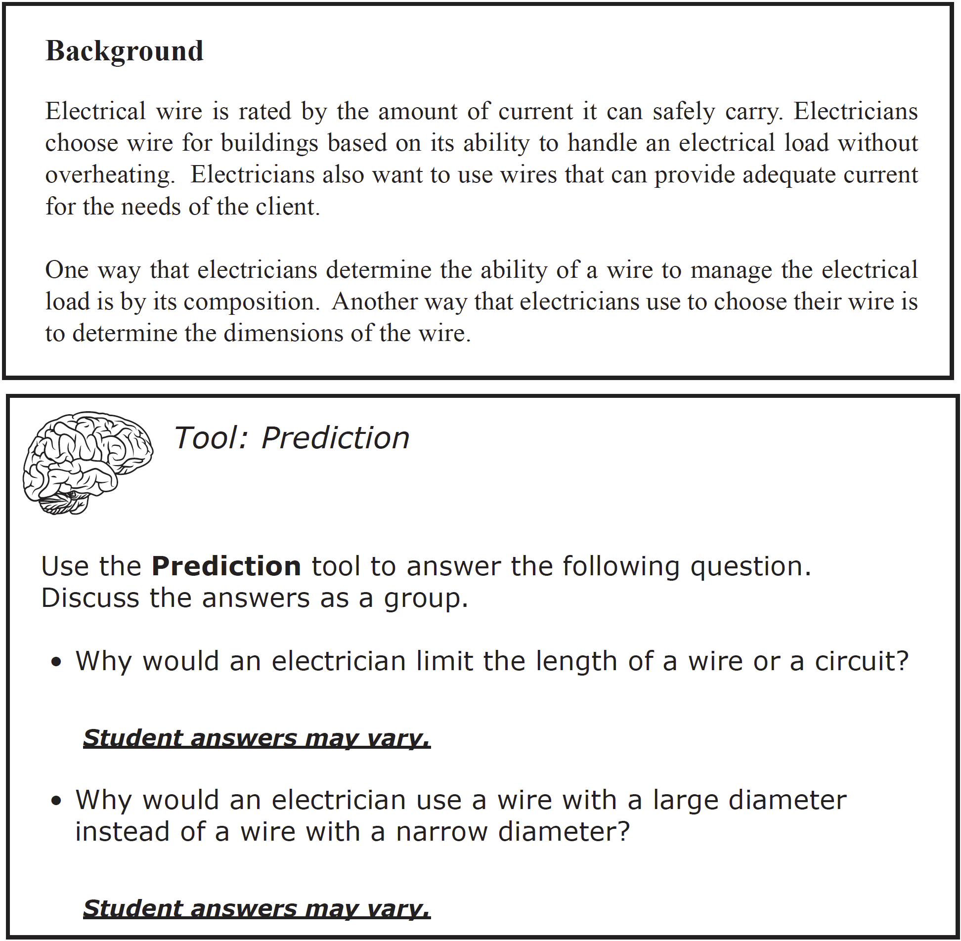
- guide students to conclude that increasing the length of a resistor decreases the amount of current in a circuit by increasing resistance, and
- demonstrate to students that increasing the cross-sectional area of a resistor increases the amount of current in a circuit by decreasing the resistance.
BE PREPARED
Teacher Preparation for the Investigation includes the following. This preparation should be done prior to students arriving in the lab.
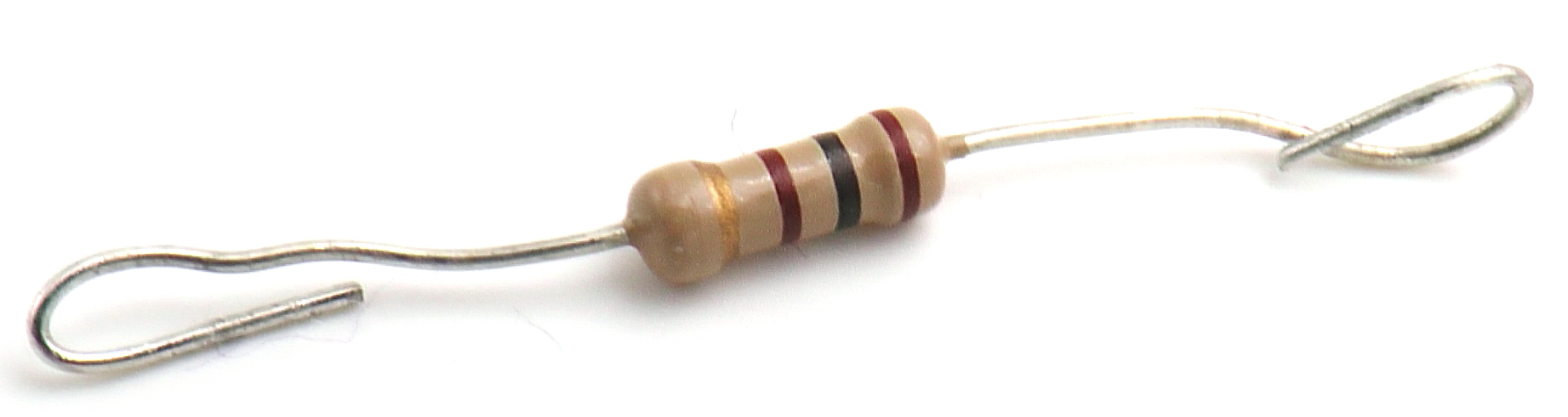
1. Remove any existing tags/tape from the 100 Ω, 470 Ω, or 1000 Ω resistors. If this is difficult, cut a small piece of masking tape to place over the lettered “flag” portion of the existing tape in order to cover up the existing label. Then move to number 2e in the instructions below.
2. Label the resistors with small masking tape flags as follows:
a. Cut two (2) piece of masking tape 10 cm long.
b. Cut each piece tape in half into lengthwise strips.
c. Cut each strip into five (5) 2 cm pieces.
d. Wrap one (1) 2 cm piece of tape around one wire of each resistor near the
barrel, matching the ends up to create a flag.
e. Write the letter “A” on the tape flag of each 100 Ω resistor.
f. Write the letter “B” on the tape flag of each 470 Ω resistor.
g. Write the letter “C” on the tape flag of each 1000 Ω resistor.
3. Cut ten (10) 5 cm pieces of tape.
4. Place all materials at a central distribution center.
5. Divide the class into five cooperative groups.
Student Preparation for the Investigation includes having students gather the following materials. This preparation takes place on lab day after student lab groups have settled at their assigned lab tables.
Note: The materials are listed in students’ SDRs. They are also listed below for your reference.
- 1 multimeter
- 2 alligator test leads
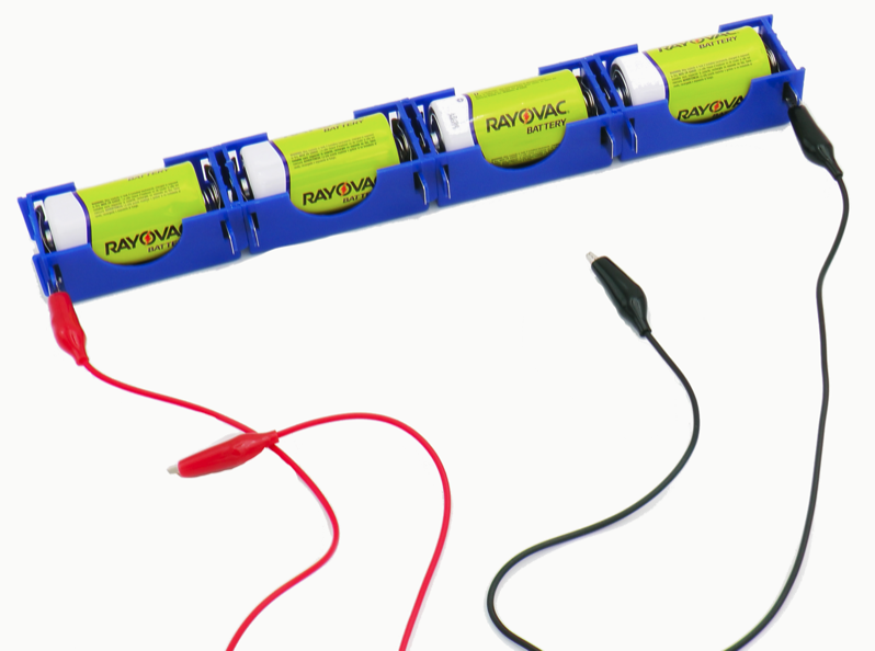
- 4 D cell batteries
- 4 D cell battery joiners
- 1 resistor A
- 1 resistor B
- 2 Resistor C
- 1 roll of masking tape
- 1 clear plastic metric ruler
Direct one student from each lab group to collect the materials listed in their SDRs.

INVESTIGATE
-
Inform students that in Trial 1, they will construct a circuit to test how changing the resistance affects the current.
- Encourage students to reflect on the PreLab video as they move through the procedural steps.
- Explain to students that during the Experiment, every procedural step is important. If one step is skipped, data can become invalid. To help students keep on track, direct them to read each step thoroughly, complete the step, then check it off (Read it – Do it – Check it off).
- Direct students to complete the procedural steps in their SDRs.
Note: The procedural steps are listed below for your reference. Teacher “Notes” are inserted, as needed, to help facilitate the lab.
Note: Most of the illustrations in the lab protocol can be enlarged for detail by clicking on the image.

Trial 1: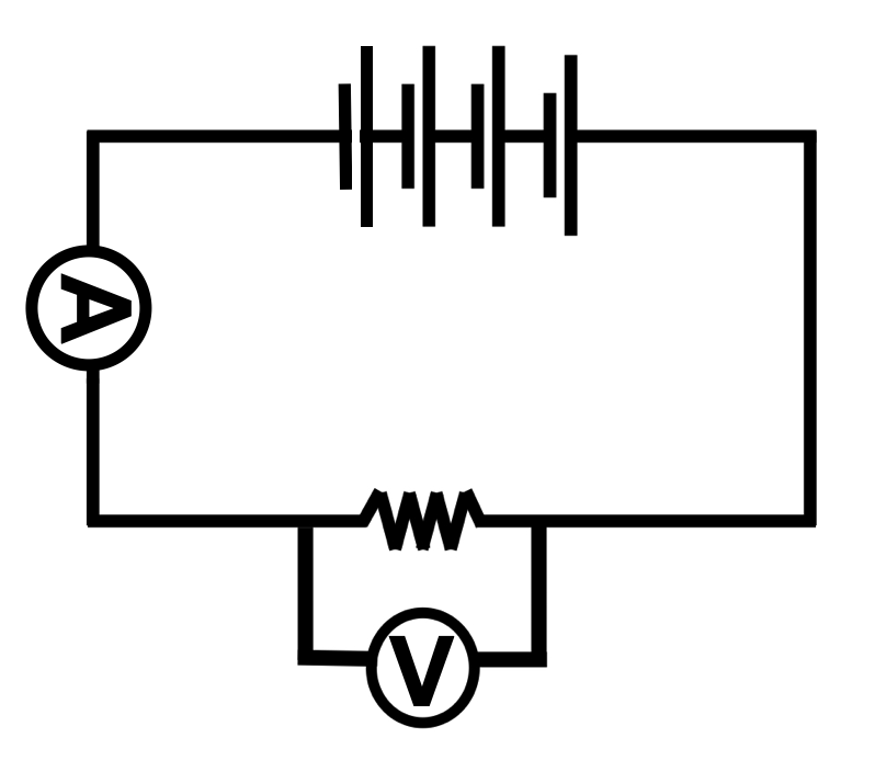

1. Construct a circuit with four batteries and one Resistor A.
a. Attach one end of an alligator test lead to the tab at the positive terminal of the group of battery joiners.
b. Attach one end of the second alligator test lead to the tab at the negative terminal of the group of battery joiners.
c. Create a small loop at each end of Resistor A.
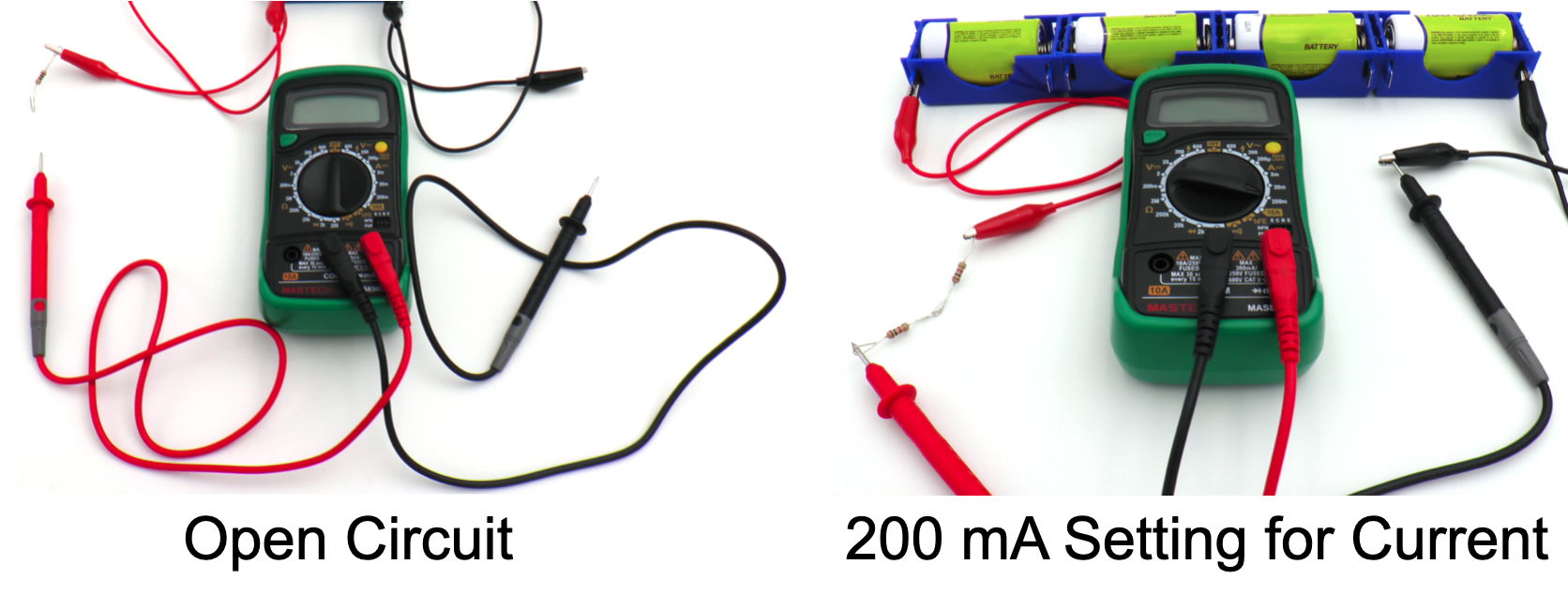
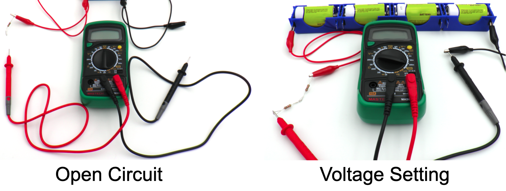
 2. Insert the ammeter (multimeter that will measure current) into the circuit. Refer to the Multimeter Use and Operation procedure for assistance if necessary.
a. Place the connector of a red probe into the outlet marked “10ADC” on the front of the multimeter.
b. Place the connector of the black probe into the outlet marked “COM” on the front of the multimeter.
c. Turn the selection dial on the multimeter to the 10A mark in the A section. This sets the multimeter to measure Amps.
 3. Measure the current of the circuit.
a. Insert the tip of the red probe from multimeter into the loop on the free end of Resistor A.
b. Insert the tip of the black probe from the multimeter into the alligator test lead connected to the negative terminal of the battery.
c. Observe the current flowing through the circuit by reading the display on the multimeter.
d. If the current is less than 0.2 A, adjust the multimeter to the 200 mA (milliamp) range to change the sensitivity of the multimeter.
• Open the circuit. Remove the black probe from the alligator test lead and the red probe from Resistor A
• Turn the selection dial to the “Off “ position. Remove the connector of the red probe from the 10ADC outlet and into the VΩmA outlet.
• Turn the selection dial to the 200 mA mark in the DCA range.
• Close the circuit. Insert the black probe into the alligator test lead connected to the negative terminal of the battery.
• Insert the red probe into the loop on the free end of Resistor B.
• Record the current in units of mAmps (mA).
e. If the current is less than 20 mA, open the circuit. Turn the selector dial to 20 mA then close the circuit and record the current in units of mAmps (mA).
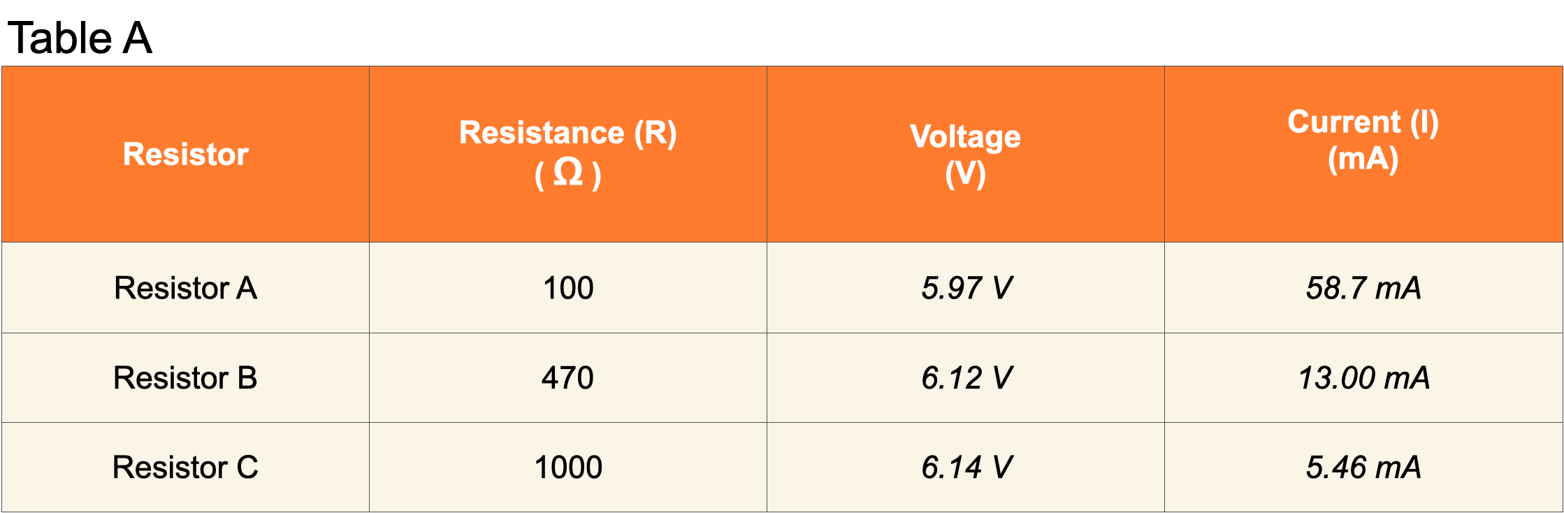
4. Record the current displayed on the multimeter in Table A.
5. Determine the voltage of the circuit across Resistor A as follows:
a. Open the circuit. Remove the black probe from the alligator test lead. Remove the red probe from Resistor A.
b. Make sure the connector of the black probe is in the outlet marked “COM” on the front of the multimeter.
c. Make sure the connector of the red probe is in the outlet marked VΩmA.
d. Turn the selection dial to 20V in the voltage section.
e. Close the circuit. Place the tip of the red probe against the alligator test lead connecting the resistor to the positive terminal of the battery.
f. Place the tip of the black probe into the alligator test lead connecting the resistor to the negative terminal of the battery.
g. Record the voltage in Table A of the Student Data Record.
h. Open the circuit by removing the black probe from Resistor A. Turn the selection dial on the multimeter to “Off.”
6. Replace Resistor A with one Resistor B. Determine the current and voltage of the circuit. Record your data in Table A.
7. Replace Resistor B with one Resistor C. Determine the current and voltage of the circuit. Record your data in Table A.
8. Question: What effect did increasing resistance have on the current flowing through the circuit?
Current decreased from 58.7 mA to 5.46 mA as resistance was increased by changing the resistor.
9. Question: How can you explain the results of your experiment in relation to Ohm’s law?
Ohm’s law states that V=IR. In this experiment, voltage remained constant while resistance increased. Because voltage stayed the same, the current had to decrease as resistance increased to maintain the relationship between voltage, current, and resistance.
Trial 2:
1. Build a circuit with four batteries and one Resistor C.
2. Refer to the diagram below for assistance if necessary.
 3. Measure the length of the resistor
barrel. Record the value in Table B of the Student Data Record.
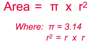
4. Calculate: Determine the cross-sectional area of the resistor barrel:
a. Measure the diameter of the barrel.
b. Divide the diameter by 2 to get the radius.
c. Use the following formula to calculate the area and record the area in Table B of the Student Data Record.

5. Determine the voltage and current as you did in Trial 1. Record the values in Table B.
Trial 3:
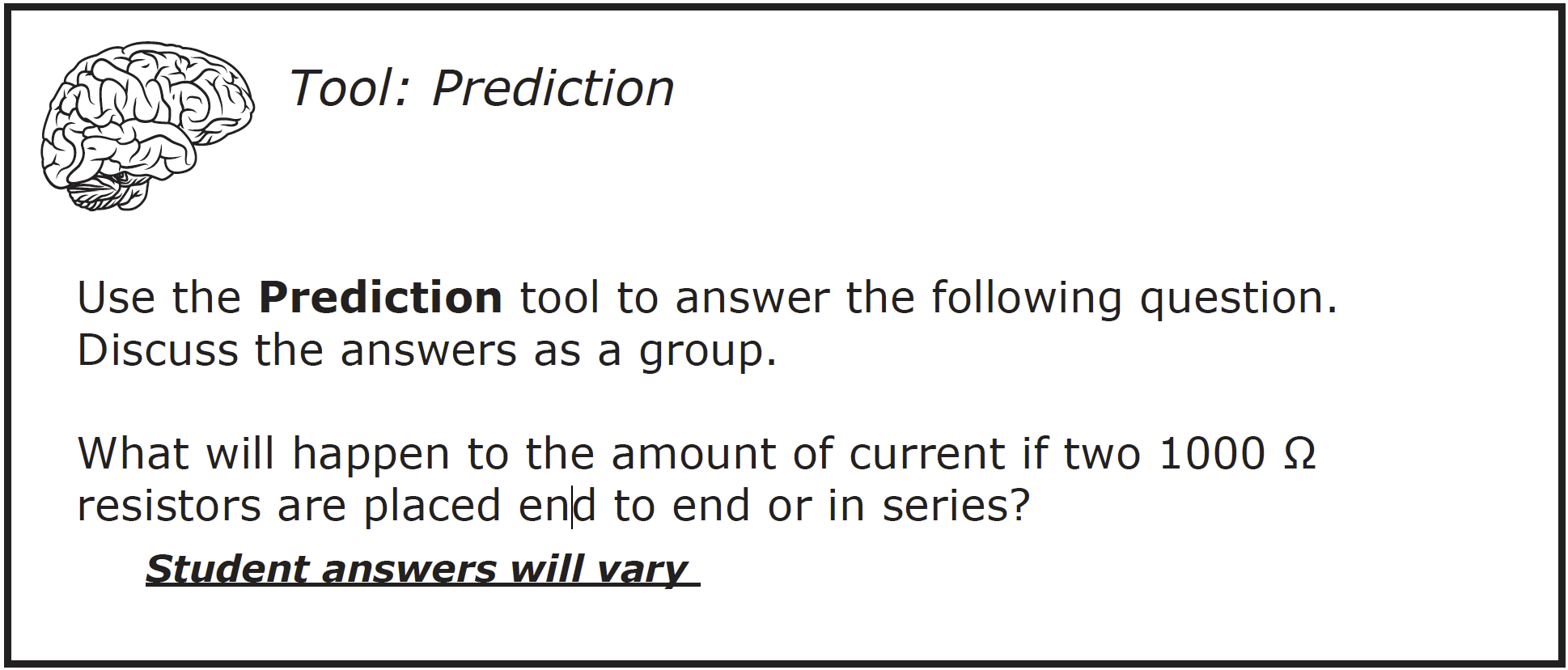
1. Construct a circuit with two 1000 Ω resistors in series as shown in the figures below.
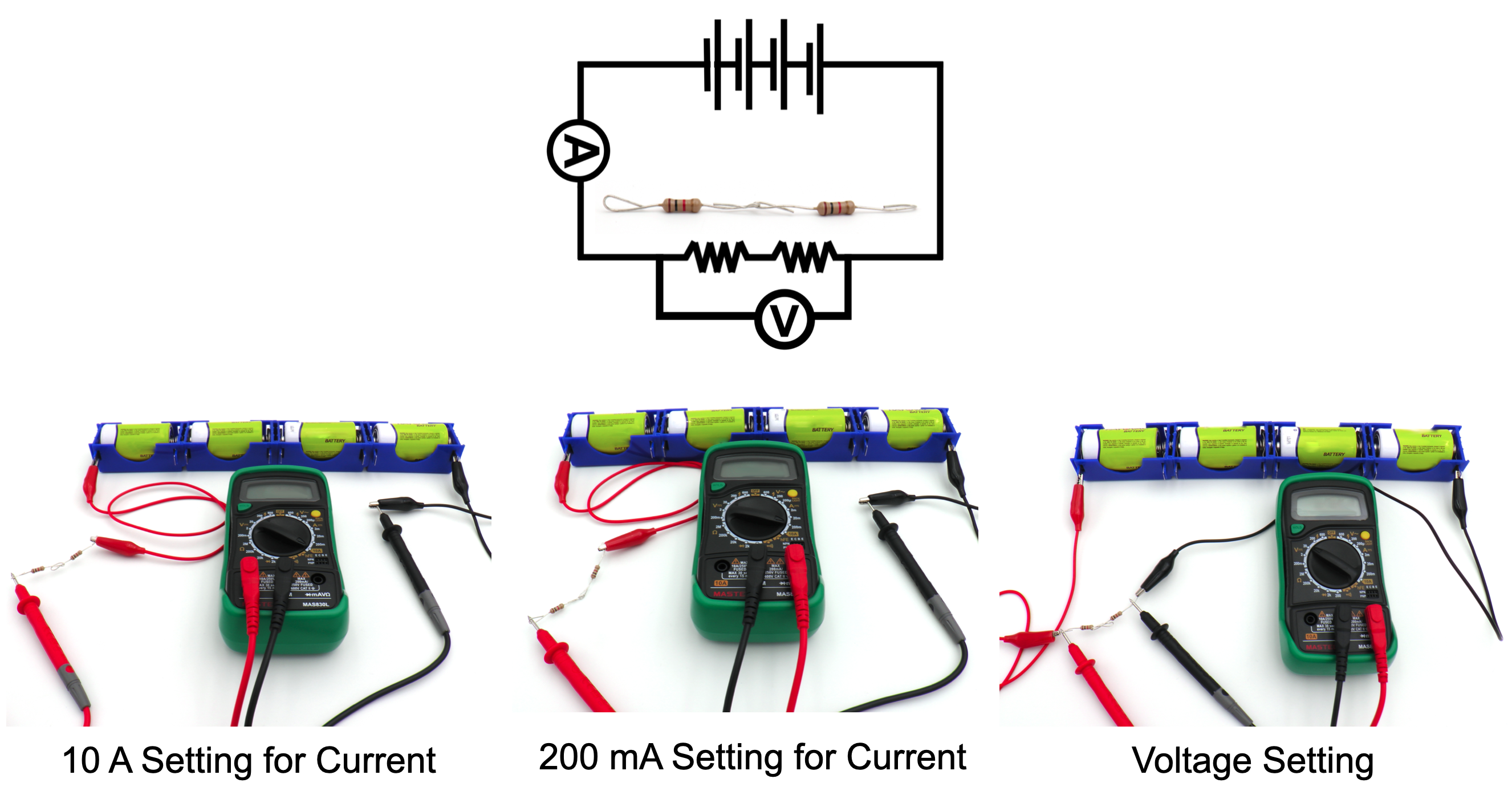
2. Record the voltage and current in Table B.
3. Question: How did adding a second resistor in series with the first resistor affect the current in the circuit?
Current decreased from 5.47 mA to 2.68 mA.
4. Calculate: Determine the length and cross-sectional area of the two 1000 Ωresistors when placed end to end or in series as follows:
a. Measure the length of the barrel of each resistor. Add the two lengths to get the length.
b. Measure the diameter of one resistor barrel.
c. Calculate the cross-sectional area of the barrel using the formula:
d. Record the data in Table B.
Trial 4:
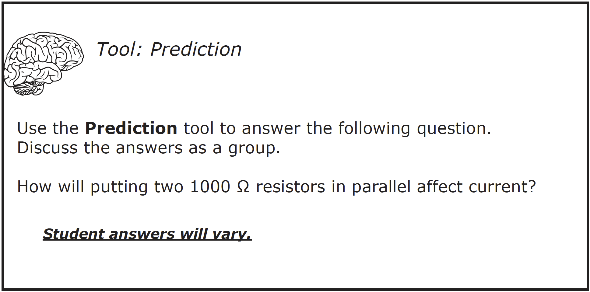
1. Construct a circuit with two resistors in parallel as shown in the picture and diagram below and record the current and voltage in Table B.
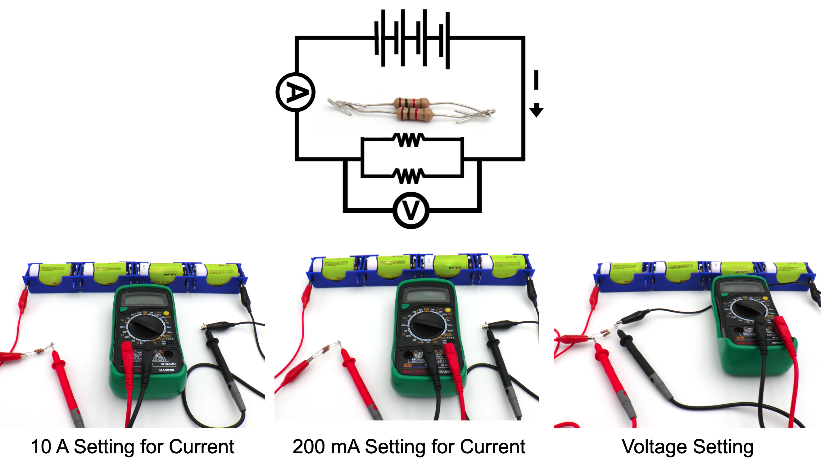
2. Question: How did adding a resistor in parallel affect the amount of current compared to the single 1000 Ω resistor?
Compared to using the single resistor, the current doubled from 5.47 mA to 10.71 mA when a second resistor was placed in parallel to the first one.
3. Measure the length of the barrel of one resistor. Record this length in Table B.
4. Calculate: Determine the cross-sectional area of the two 1000 Ω resistors when placed in parallel as follows:
a. Measure the diameter of each resistor barrel.
b. Calculate the cross-sectional area of each barrel using the formula:
c. Add the two areas to determine the total cross-sectional area of the resistors in parallel.
d. Record the data in Table B.
5. Question: Look at the data for resistor length. Do you think the length of a resistor affects current? Explain your answer.
The length of a resistor affects current because putting two resistors in series increased the length and affected current compared to a single resistor.
6. Question: Look at the data for the cross-sectional area. Do you think the cross-sectional area affects current? Explain your answer.
The cross-sectional area affects current because putting two resistors in parallel increased the cross-sectional area and affected current compared to a single resistor.
7. Question: Do the cross-sectional area and length of the resistor affect current the same way? Explain your answer.
They do not affect current the same way. Increasing length decreases current while increasing cross-sectional area increases current.

CLEAN UP
Let students know your expectations for cleanup. Ask them to clean up.