Teacher Portal:
Electricity and Magnetism
Investigation 1 – Lab

ZERO-IN
Italicized font represents information to be shared orally or physically completed with the students at this time.
The non-italicized font represents additional information included to support the teacher’s understanding of the content being introduced within the CELL.
MINDSET
This Investigation is designed to:
- illustrate to students that the amount of current in a circuit is proportional to the amount of voltage supplied by the power source,
- allow students to discover that the ratio of voltage to current is constant regardless of the amount of voltage,
- allow students to conclude that the ratio of voltage to current is resistance, and
- establish that the relationship between voltage, current, and resistance is Ohm’s Law.
BE PREPARED
Teacher Preparation for the Investigation includes the following. This preparation should be done prior to students arriving in the lab.
- Label (5) 100 Ω resistors as “A” with a small masking tape flag as follows:
- Cut one (1) piece of masking tape 10 cm long.
- Cut the tape in half lengthwise.
- Cut each strip into five (5) 2 cm pieces.
- Wrap one (1) 2 cm piece of tape around one wire of each resistor near the barrel, matching the ends up to create a flag.
- Write the letter “A” on the tape for each resistor.
- Repeat the steps above with the five (5) 1000 Ω resistors with the remaining strip of tape. Label the five (5) 1000 Ω resistors as “B.”
- Cut ten (10) 5 cm pieces of tape.
- Place all materials at a central distribution center.
Note: Each student lab group will need the materials listed below.
- Divide students into cooperative groups of five students.
Student Preparation for the Investigation includes having students gather the following materials. This preparation takes place on lab day after student lab groups have settled at their assigned lab tables.
Note: The materials are listed in students’ SDRs. They are also listed below for your reference.
- 1 multimeter
- 2 alligator test leads
- 3 D cell batteries
- 3 D cell battery joiners
- 1 resistor A
- 1 resistor B
- 1 roll of masking tape
- 1 clear plastic metric ruler
Direct one student from each lab group to collect the materials listed in their SDRs.


INVESTIGATE
- Inform students that during this Investigation, they will begin their examination of the relationship between voltage, current, and resistance by studying what happens to current when the amount of voltage in a circuit changes.
- Encourage students to reflect on the PreLab video as they move through the procedural steps.
- Explain to students that during the Experiment, every procedural step is important. If one step is skipped, data can become invalid. To help students keep on track, direct them to read each step thoroughly, complete the step, then check it off (Read it – Do it – Check it off).
- Direct students to complete the procedural steps in their SDRs.
Note: The procedural steps are listed below for your reference. Teacher “Notes” are inserted, as needed, to help facilitate the lab.
Note: Most of the illustrations in the following lab protocol can be enlarged to see details by clicking on the image.
__________________________________________
Trial 1:
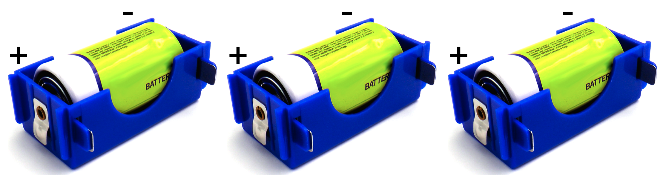
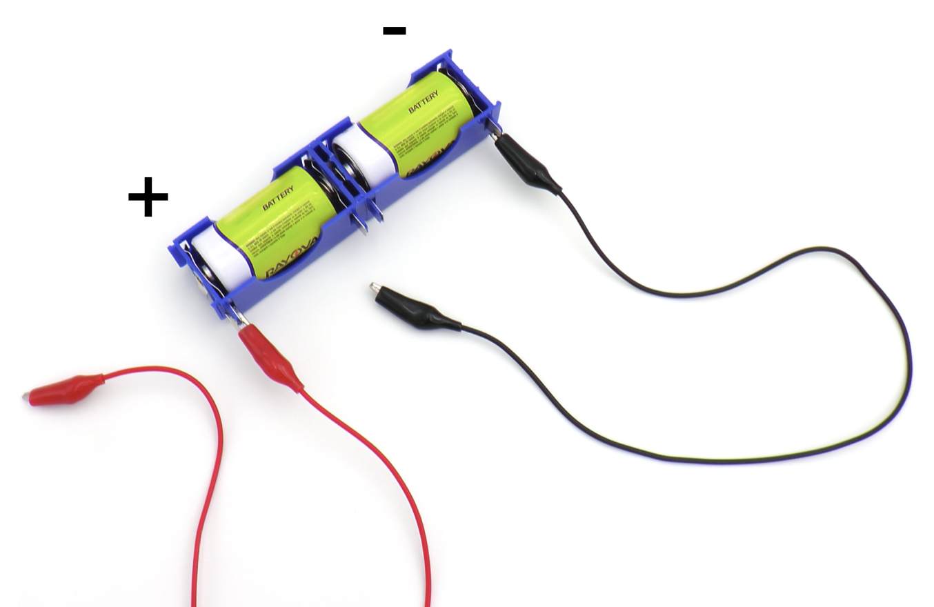
1. Place the batteries in the battery joiners. Make sure that the positive terminals of the batteries are turned to the positive ends of the battery joiners.
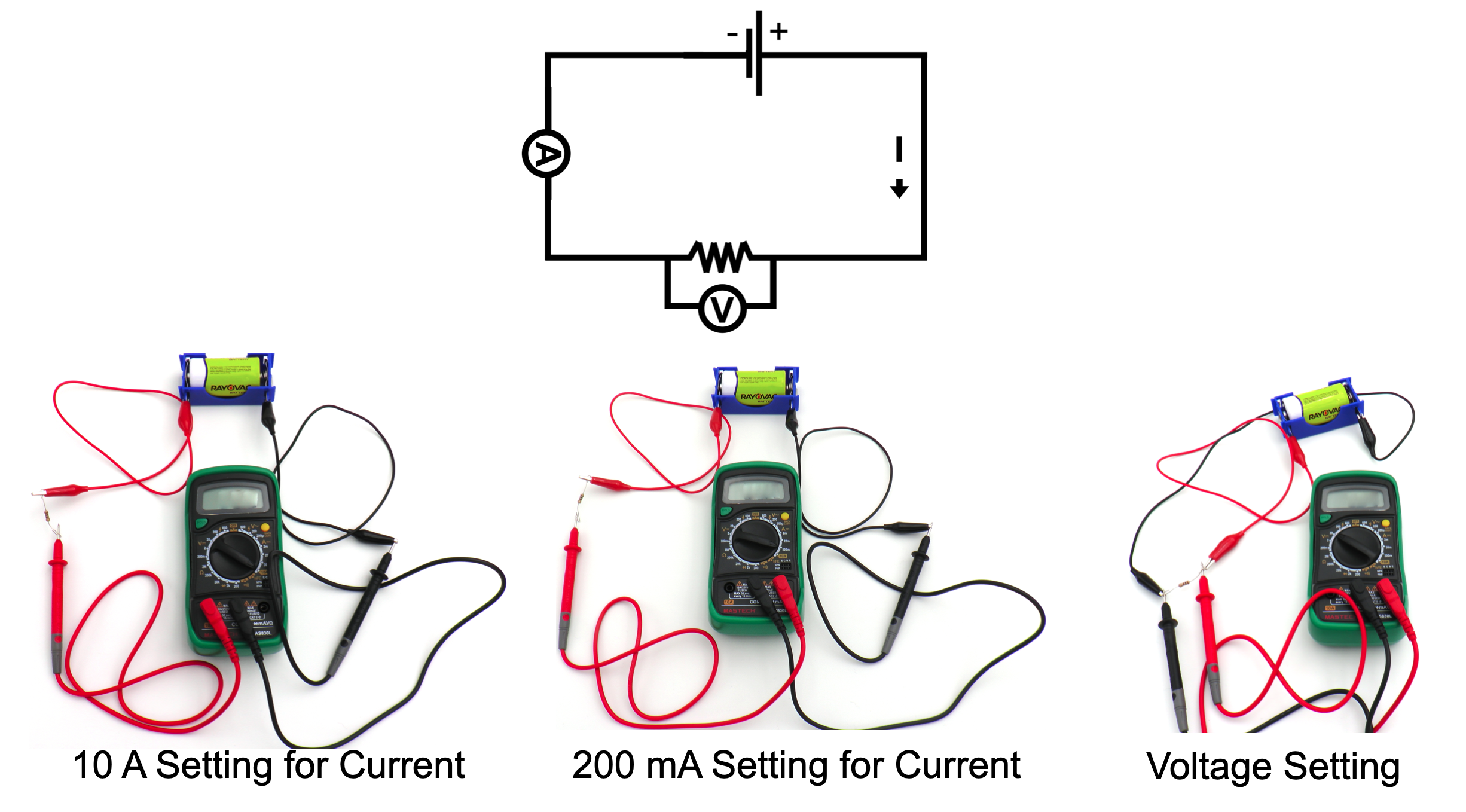
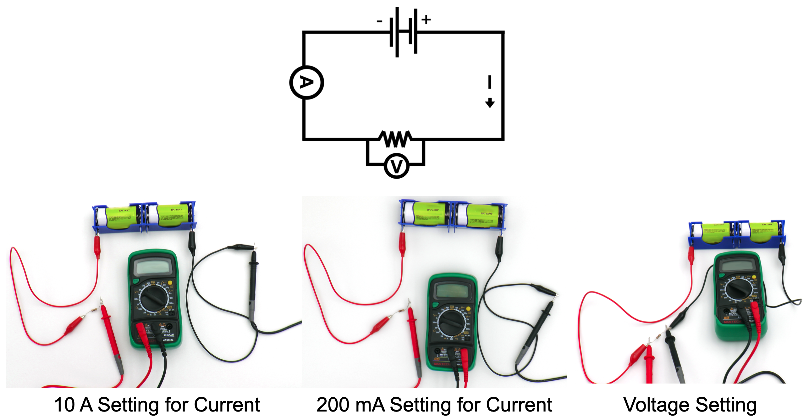
2. Construct a simple circuit with a single battery and Resistor A as shown below using the following steps (Note: The voltmeter/ ammeter will be added after the circuit is constructed):
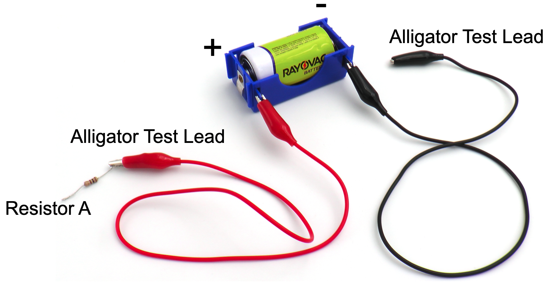
A. Attach one end of an alligator test lead to the tab at the positive terminal of one battery joiner.
B. Attach one end of the second alligator test lead to the tab at the negative ![]() terminal of the battery joiner.
terminal of the battery joiner.
C. Create a small loop at each end of Resistor A.
D. Connect the end of the alligator test lead from the positive terminal to the wire at one end of Resistor A.
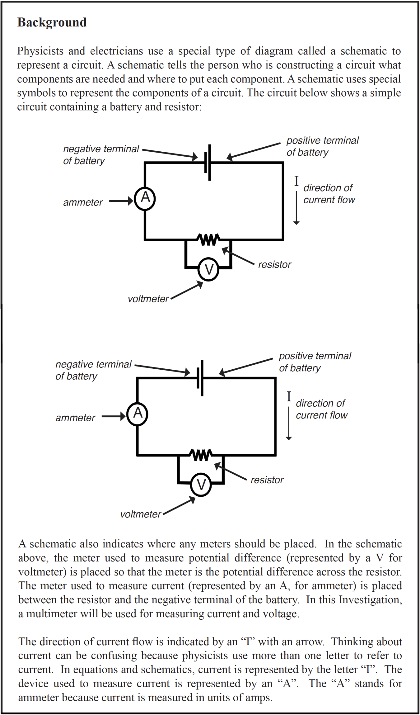
 3. Insert the ammeter (multimeter that will measure current) into the circuit. Refer to the Multimeter Use and Operation procedure for assistance if necessary.
A. Place the connector of a red probe into the outlet marked “10ADC” on the front of the multimeter.
B. Place the connector of the black probe into the outlet marked “COM” on the front of the multimeter.
 C. Turn the selection dial on the multimeter to the 10A mark in the A section. This sets the multimeter to measure Amps.
4. Measure the current of the circuit.
A. Insert the tip of the red probe from the multimeter into the loop on the free end of Resistor A.
B. Insert the tip of the black probe from the multimeter into the alligator test lead connected to the negative terminal of the battery.
C. Observe the current flowing through the circuit by reading the display on the multimeter.
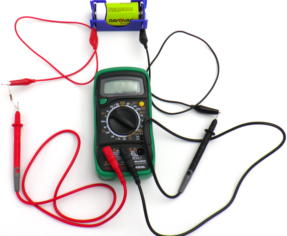
10A setting for current
D. If the current is less than 0.2 A, adjust the multimeter to the 200 mA (milliamp) range to change the sensitivity of the multimeter.
– Open the circuit. Remove the black probe from the alligator test lead and the red probe from Resistor A.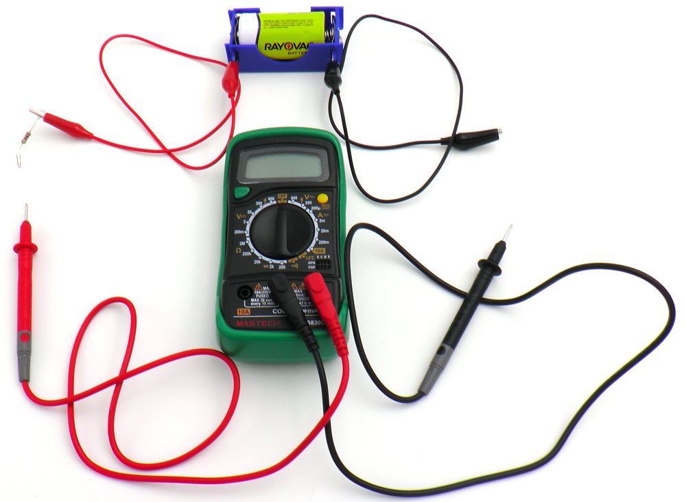
– Turn the selection dial to the “Off “ position. Remove the connector of the red probe from the 10ADC outlet and into the VΩmA outlet.
– Turn the selection dial to the 200 mA mark in the DCA range.
– Close the circuit. Insert the black probe into the alligator test lead connected to the negative terminal of the battery.
– Insert the red probe into the loop on the free end of Resistor A.
– Record the current in units of mAmps (mA).
E. If the current is less than 20 mA, open the circuit. Turn the selector dial to 20 mA then close the circuit and record the current in units of mAmps (mA).
5. Record the current displayed on the multimeter in Table A.
6. Determine the voltage of the circuit across Resistor A as follows:
A. Open the circuit. Remove the black probe from the alligator test lead. Remove the red probe from Resistor A.
B. Make sure the connector of the black probe is in the outlet marked “COM” on the front of the multimeter.
C. Make sure the connector of the red probe is in the outlet marked VΩmA.
D. Turn the selection dial to 20V in the voltage section.
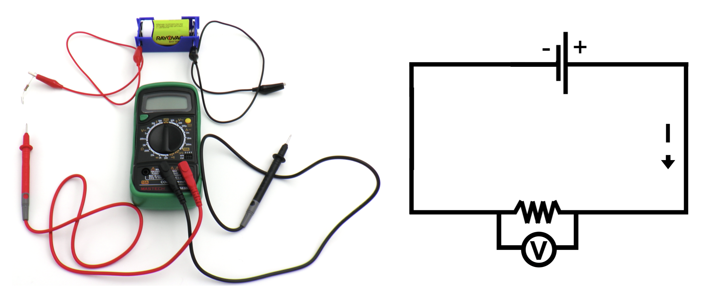
E. Close the circuit. Place the tip of the red probe against the alligator test lead connecting the resistor to the positive terminal of the battery.
F. Place the tip of the black probe into the alligator test lead connecting the resistor to the negative terminal of the battery.
G. Record the voltage in Table A.
H. Open the circuit by removing the black probe from Resistor A. Turn the selection dial on the multimeter to “Off.”
___________________________________________
Trial 2:
- Add a second battery to the circuit.


A. Disconnect the alligator test leads from the battery joiner.
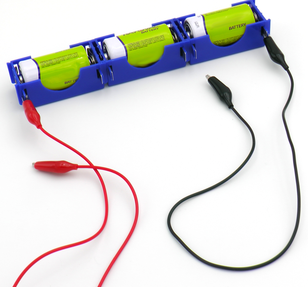
B. Place a second battery joiner with the battery next to the first. Turn the positive terminal of the new battery so that it is against the negative terminal of the first battery.
C. Connect the battery joiners by sliding them together.
D. Connect the alligator test leads to the negative and positive terminals of the battery joiners.
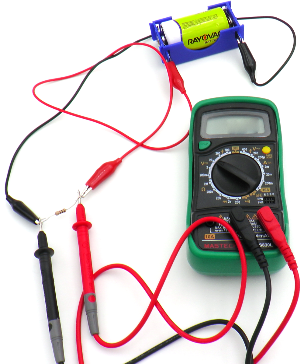
2. Determine the voltage and current of the new circuit as you did in Trial One. Record the values in Table A.
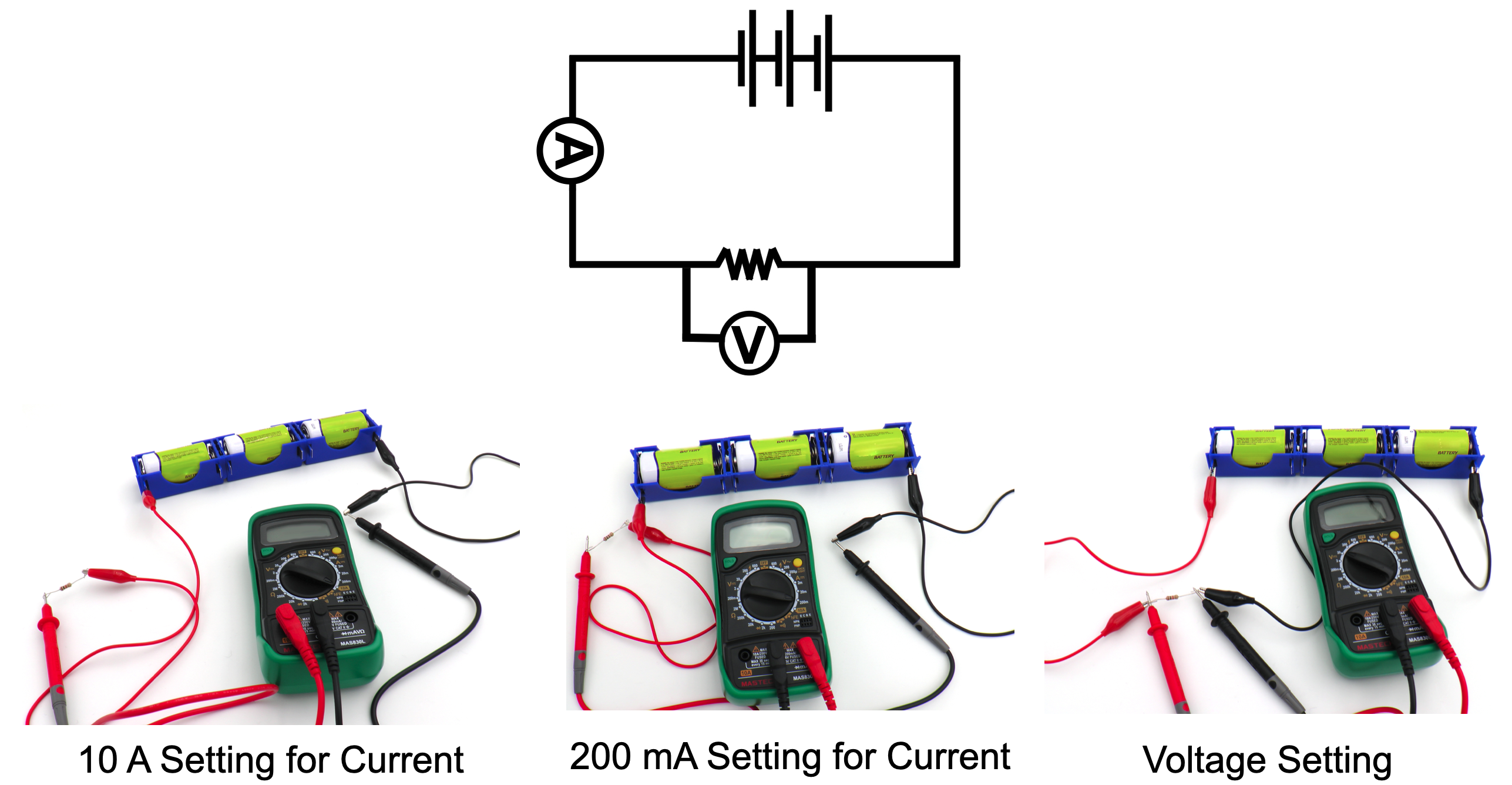
3. The circuits for determining current and voltage should look similar to the pictures below.

4. Open the circuit. Turn the selection dial on the multimeter to “Off.”
___________________________________________
Trial 3:
1. Add the third battery to the circuit shown below as follows:
2. Determine the voltage and current of the new circuit. Record the values in Table A.
3. Observe the data in Table A. What effect did increasing the number of batteries have on voltage? Voltage increased as the number of batteries increased.
4. What effect did increasing the number of batteries have on the current flowing through the circuit? Current increased as the number of batteries increased.
5. Did you see a pattern in the voltage? What about the current? Voltage increased by approximately 1.5 V each time a battery was added. Current increased by approximately 15 mA each time a battery was added.
6. Think about what happened to the voltage and the current as the number of batteries increased. How would you describe the relationship between voltage and current? There is a direct relationship between voltage and current because when one changes, the other changes in the same manner.
___________________________________________
Trial 4
- Build a circuit with a single battery and Resistor B. Refer to the figures below for assistance if necessary.
2. Determine the voltage and current. Record the values in Table B of the Student Data Record.
3. Add a second battery to the circuit as shown in the figures below. Record the voltage and current in Table B.
4. Add the third battery to the circuit as shown in the figures below. Record the voltage and current in Table B.
5. What effect did increasing the number of batteries have on voltage in this circuit? Voltage increased as the number of batteries increased.
6. What effect did increasing the number of batteries have on the current flowing through this circuit? Current increased as the number of batteries increased.
7. Did you see a pattern in the data for Resistor B? How does this pattern compare to the pattern you saw in the data with the first resistor? Current increased by approximately 1.5 mA each time a battery was added. This increase is 10 times smaller than the increase observed with the first resistor. So, there was an increase but it was much smaller.


CLEAN UP
Let students know your expectations for cleanup. Ask them to clean up.