Teacher Portal:
Electricity and Magnetism
Performance Assessment
ZERO-IN

The italicized font represents information to be shared orally or physically completed with the students at this time.
The non-italicized font represents additional information included supporting the teacher’s understanding of the content being introduced within the CELL.
MINDSET
This Investigation is designed to allow students to solve a problem using the:
- promote problem-solving skills by encouraging students to find appropriate solutions to problems,
- encourage students to apply the relationship among voltage, current, and resistance as they design three electromagnets to meet the specifications established in the opening scenario,
- encourage students to apply their knowledge of the relationship between current and magnetic field as they work together to create the three electromagnets,
- assess students’ understanding of Ohm’s Law, and
- assess students’ understanding of the effects of current and the number of coils of wire on the magnetic field.
DOWNLOAD IT – PRINT IT
By clicking the link below, the Performance Assessment Grading Rubric may be downloaded as a PDF (Portable Document Format) and printed. It is suggested that the teacher uses the printed rubric as a guide and make additional notes during the assessment.
BE PREPARED
Teacher Preparation for the Investigation includes the following. This preparation should be done prior to students arriving in the lab.
1. Cut ten (10) 75 cm pieces of wire with the wire cutters. Use the wire cutters to strip approximately 1 cm of insulation from the ends of each piece of the newly cut wire.
2. Place all materials at a central distribution center.
3. Divide the class into groups of three.
Note: In the previous three Investigations, students conducted experiments designed to demonstrate the concepts of Ohm’s Law and the relationship between current and magnetic field. In this Performance Assessment, students will create their own experiments to test electromagnets that they will design based on an assigned problem.
INVESTIGATE
1. Direct one student from each group to obtain the following materials from the central distribution center: two (2) alligator test leads, one (1) 100 cm piece of wire, one (1) multimeter, one (1) nail, two (2) batteries, two (2) battery joiners, one (1) 100 Ω resistor, one (1) 470 Ω resistor, one (1) 1000 Ω resistor, and twenty (20) paper clips.
2. Direct students to read the Background section at the beginning of the Student Data Record.
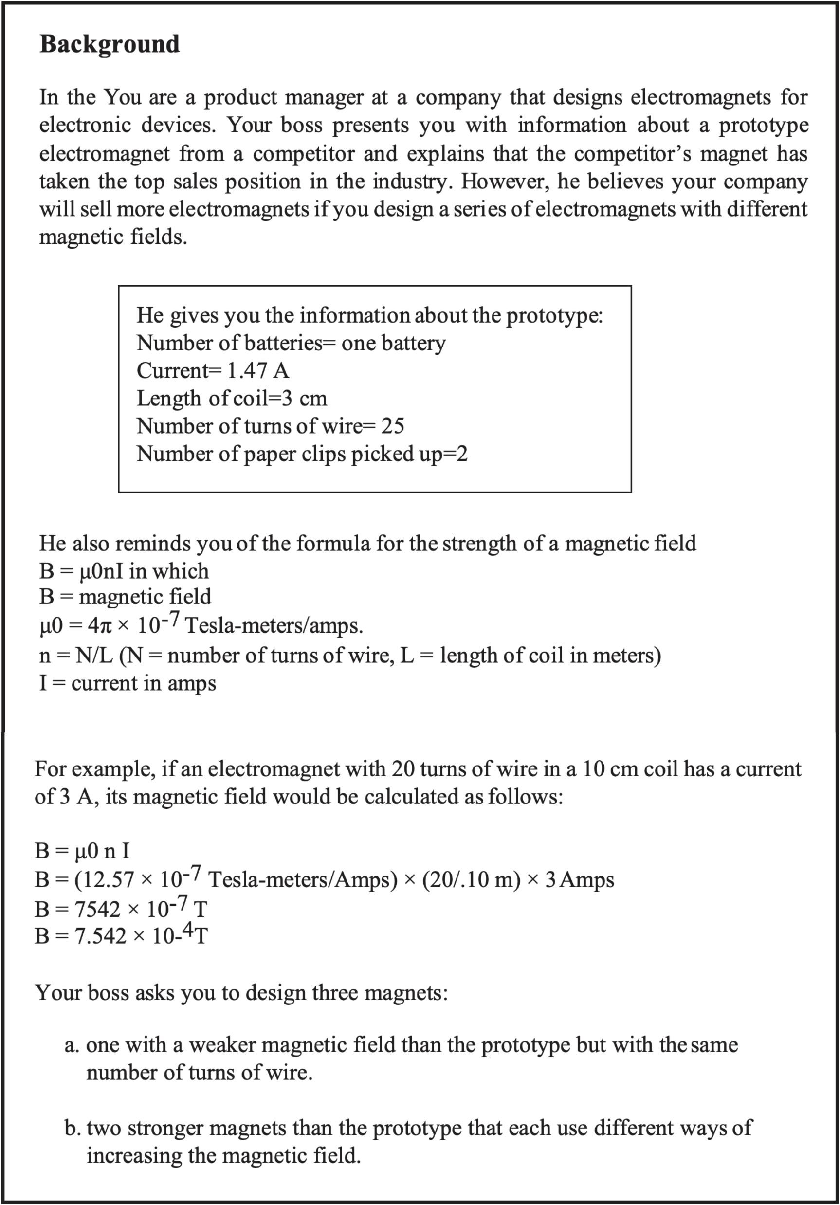
3. Briefly review with students the requirements for creating the three electromagnets and explain that all the information needed to complete the Performance Assessment is provided in the Background.
4. Read aloud the goals of the Performance Assessment or ask for student volunteers to read the Goals aloud:
- Design an electromagnet that is weaker than the prototype but uses the same number of turns of wire.
- Design two electromagnets that are stronger than the prototype, each using different methods to increase the magnetic field.
- Explain how you plan to compare your magnets against the prototype.
- Construct the electromagnets and test each against the prototype.
- Explain whether your designs for each electromagnet were successful and why.
5. Before students begin their projects, walk through the five steps of the Performance Assessment with the students. Explain to students that they are to draw on their understanding of the concepts learned in Investigations One through Three to design their electromagnets to meet the requirements stated in the Background section.
6. Allow students to complete their Performance Assessments. You may choose to assess the students formally or informally as they work to complete the assignment.
EXPERIMENT
- Design an electromagnet that is weaker than the prototype but uses the same number of turns of wire.
a. Draw a diagram of the electromagnet and write a description of each design to the right of the diagram. Student answers will vary. A sample design is pictured below. The answers for the remaining problems will reflect information and data based on the sample design.
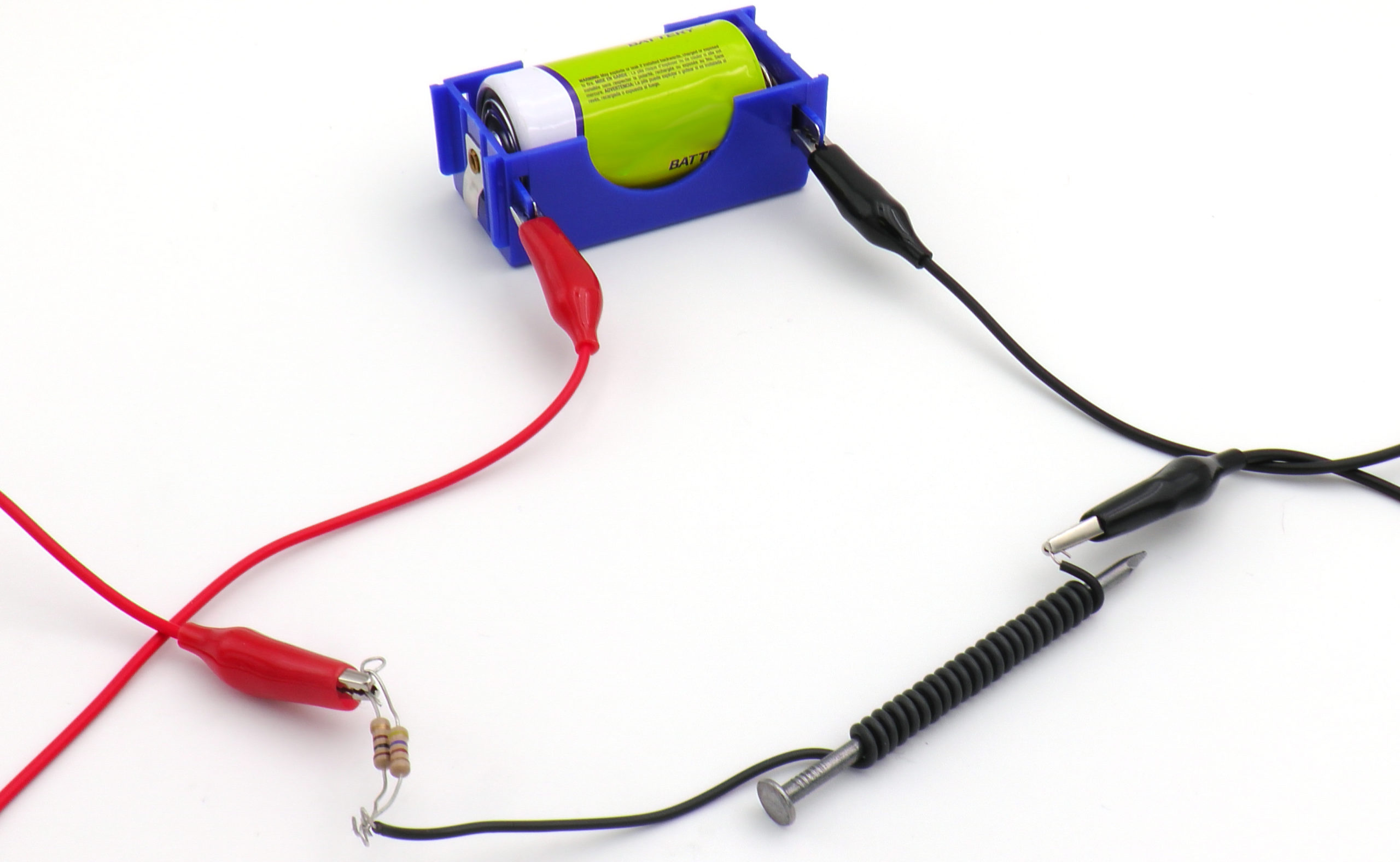
A nail will be wrapped with 25 turns of wire and connected to a single battery. A 100 Ω resistor and a 470 Ω resistor will be placed in parallel with each other between the battery and the electromagnet to reduce the flow of current.
b. Explain why you chose the materials and design used in this electromagnet. The prototype has the fewest number of batteries possible, so current cannot be decreased by decreasing the number of batteries in the weaker magnet. The magnetic field cannot be decreased by decreasing the number of turns because the weaker magnet must have 25 turns of the wire. Therefore, the only way to decrease the magnetic field is to decrease the amount of current by adding resistance to the circuit. The two smallest resistors available are 100 Ω and 470 Ω, so one of each will be used in parallel to limit the amount of resistance being added to the circuit.
2. Design two electromagnets that are stronger than the prototype, each using different methods to increase the magnetic field. Draw diagrams and describe each design in the space below.
a.Draw a diagram of each electromagnet and write a description of each design to the right of the diagram. Student answers will vary. A sample design is described below. The answers for the remaining questions will reflect information and data based on the sample design.
 Note: Students may opt to combine increasing the number of turns of wire and increasing the number of batteries. Should students choose this option discussed in the next question should demonstrate an understanding that each factor increases magnetic field in a different fashion.
b. Explain why you chose your materials and designs used in each electromagnet. For the stronger magnets, the magnetic field of one electromagnet will be increased by increasing the flow of current through the addition of a battery. The magnetic field of the second stronger magnet will be increased by increasing the number of turns of wire rather than by increasing the amount of current in the circuit. Increasing both the current and the number of turns of wire should also increase the magnetic field because both options increase magnetic field when used alone.
3. Explain how you plan to compare your magnets against the prototype. Magnets will be compared against the prototype by calculating the strength of the magnetic field and by determining the number of paper clips each magnet can pick up. For calculations of magnetic field, current and length of each electromagnet will be measured as well as determination of the number of coils. The values for current, electromagnetic length, and number of coils will then be used to calculate the strength of the magnetic field. The magnetic field of each magnet will then be compared to the magnetic field of the prototype.
The magnetic field will also be determined by comparing the number of paper clips each electromagnet can pick up compared to the prototype. Stronger magnets are expected to have a stronger magnetic field, and therefore be able to pick up a greater number of paper clips than weaker magnets. Electromagnets with weaker magnetic fields would pick up fewer paper clips than the prototype.
Note: Both methods for determining the strength of the electromagnets are presented above. Students may choose to use both, or only one of the methods when determining the strengths of their electromagnets.
- Construct the electromagnets and test each against the prototype. Use the space below to construct a data table and perform calculations.
Note: Students are not expected to increase both the number of turns and the number of batteries. However, sample data has been included in case students choose to combine the two factors in one of their strong electromagnet designs.
5. Explain whether your designs for each electromagnet were successful and why. Present analyses and conclusions to support your explanation of why each magnet met the requirements.
a. Use the space below to present your analyses in the form of additional data tables or graphs.
Note: Students should not rely on a graph of the effect of design on current alone as sufficient evidence of design causing an increase in magnetic strength, as the strength of the magnetic field can be increased without an increase in current. Thus, students who do not cite additional evidence demonstrating the effects of design on magnetic strength have not adequately supported their conclusions. This evidence should be either in the form of data or a graph indicating an increase in the number of paper clips attracted by the magnet, or calculations, or a graph documenting the strength of the magnetic field.
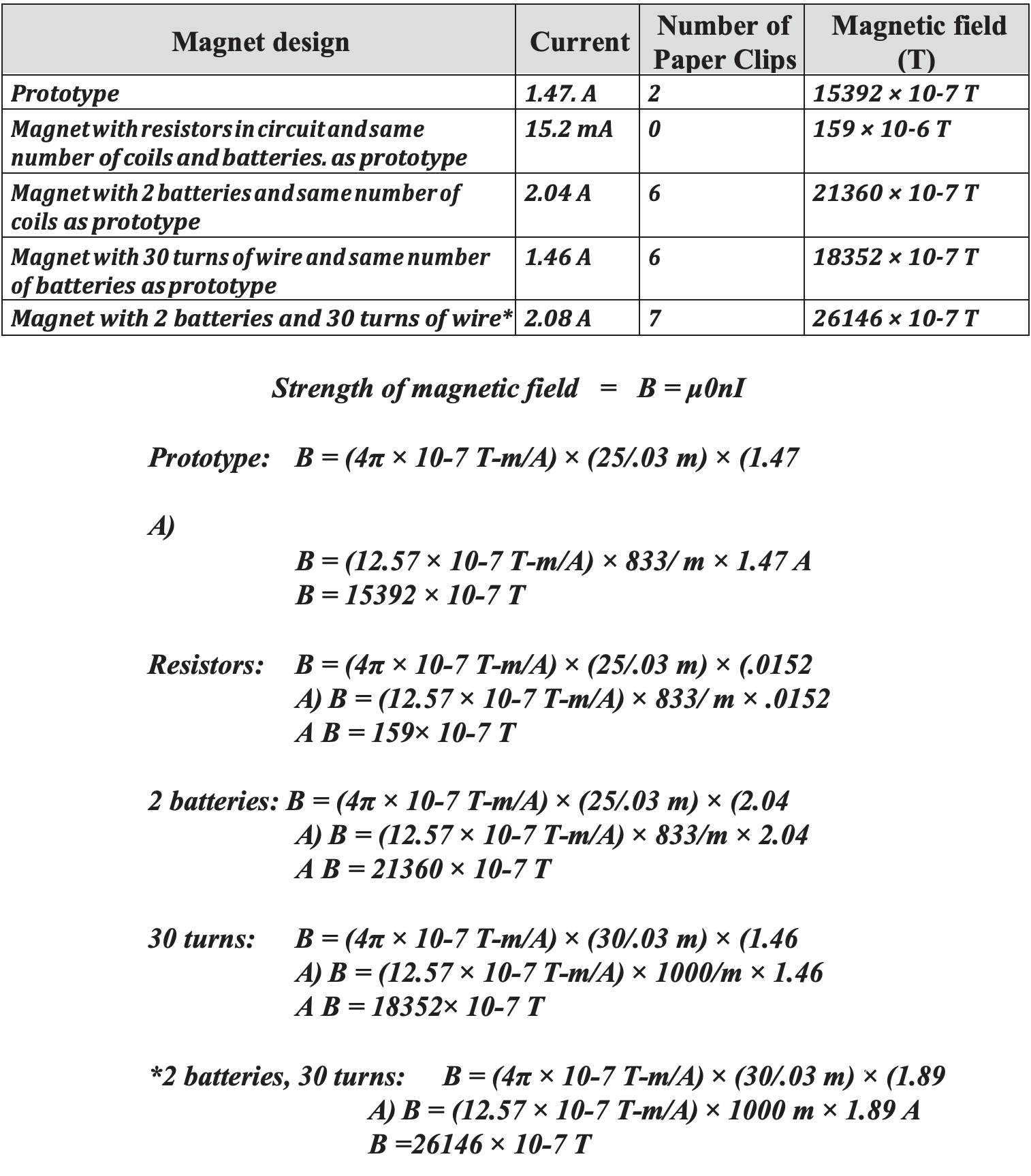
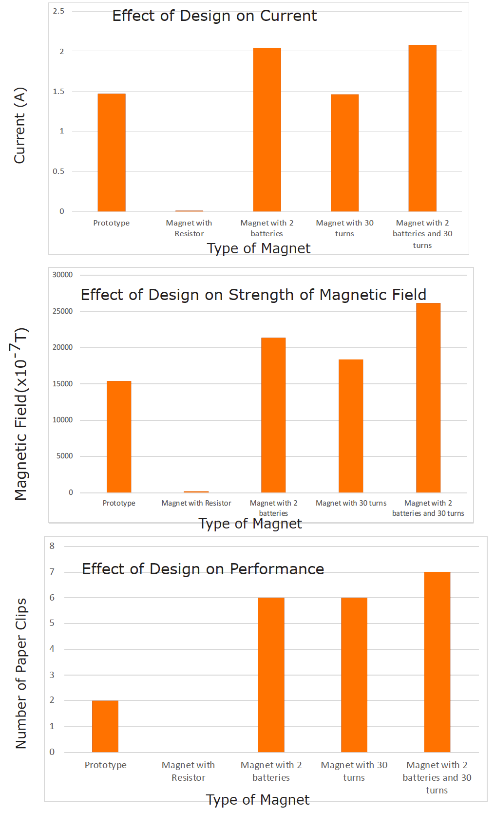
b. Use the space below to explain your conclusions. The design for the electromagnet with a weaker magnetic field was successful because including resistors reduced the current of the electromagnet and thus the strength of the magnetic field. Current has a direct effect on the strength of the magnetic field of an electromagnet. Current through the magnet decreased from 1.47 A in the prototype to 15.2 mA in the weaker magnet. Thus, the weaker magnet failed to produce a magnetic field strong enough to pick up any paper clips despite the use of resistors in parallel to lessen the potential effect of a single 100 Ω resistor on the current. The decrease was also shown by the value of 15392 × 10-7 T for the magnetic field as compared to 159 × 10-7 T for the prototype.
The two stronger magnets were also successful. The electromagnet with two batteries increased the current of the magnet as compared to the prototype as shown by the changes in current in the graph above. The magnet with two batteries had a current of 2.04 A, which was greater than the 1.47 A of the prototype. The stronger magnet was able to hold 4 paper clips, 2 more than the prototype magnet. In addition, the strength of the magnetic field was 21360 × 10-7 T as compared to 15392 × 10-7 T with the prototype.
Magnet performance was also increased by increasing the turns of wire in the coil. The magnet with 30 turns of wire had only 1.46 A of current compared to the prototype’s 1.47 A, but was able to pick up 4 more paper clips than the prototype. In addition, its magnetic field was 18352 × 10-7 T as compared to 15392 × 10-7 T of the prototype. The increase in the strength of the magnetic field for this magnet was a result of adding an additional 5 turns of wire to the magnet rather than increasing the current.
Note: Increasing the number of turns of wire as well as increasing the number of batteries also had a positive effect on the performance of the magnet. The magnet with 30 turns of wire and 2 batteries had only 2.08 A of current compared to the prototype’s 1.47 A, but was able to pick up 5 more paper clips than the prototype. In addition, the strength of the magnetic field was 26146 × 10-7 T compared to the 15392 × 10-7 T of the prototype.
CLEAN UP
Let students know your expectations for cleanup. Ask them to clean up.
ANALYZE IT
Discuss the results of the Performance Assessment as a class, including:
- all possible solutions to the posed problem,
- whether each student group met the goals of the Performance Assessment, and
- any procedural difficulties student groups had in meeting the goals.

1. During this CELL, students performed several experiments that investigated the relationships between voltage, current, resistance, and magnetism. The Investigations of the CELL addressed the following Focus Questions:
- What is the relationship between voltage, current, and resistance?
- How do the dimensions of a resistor affect current?
- What is the relationship between electricity and magnetism?
- What factors affect the strength of an electromagnet?
2. Ask students to answer the Focus Questions and to discuss their answers. Use the answers and the discussion to summarize the CELL and to informally assess students’ understanding.
a. What is the relationship between voltage, current, and resistance? The change in current in a circuit is directly proportional to the change in its voltage. As voltage increases, current increases proportionately but the resistance to the flow of current remains constant. In Investigation One, the number of batteries in each of the two circuits was increased resulting in increased voltage and current, but no change in the resistance until the resistor used in the circuit was changed. In addition, the change in current in a circuit is inversely proportional to the resistance. As the resistance in a circuit increases, the current decreases. The relationship among voltage, current, and resistance is described by Ohm’s Law, V = IR or R = V/I.
In Investigation One, two different resistors were used in two different circuits of the same voltage illustrating that the circuit with the greater resistance had a lower current than the circuit with the lesser resistance. Increasing resistance by changing resistors resulted in a decrease in current proportional to the change in resistance, but voltage remained constant at 6.15 V. In Investigation Two, resistors were placed in series and parallel within the circuit. Placing two 1000 Ω resistors in series caused the current to decrease by approximately one-half, from 5.47 to 2.68 mA. At the same time, resistance doubled from 1124 to 2295 Ω. Placing two 1000 Ω resistors in parallel caused current to double from 5.47 to 10.71 mA while resistance decreased by one-half, from 1124 to 574 Ω. In each case, the change in current and the change in resistance were inversely proportional, and voltage remained constant. These results demonstrate that Ohm’s Law applies regardless of whether there is one resistor or many resistors. Ohm’s Law also applies regardless of whether multiple resistors are placed in series or in parallel.
b. How do the dimensions of a resistor affect current? In Investigation Two, it was shown that increasing the length of a resistor by placing two equal resistors in series doubled the resistance from 1124 Ω to 2295 Ω. This caused the current to decrease by half, from 5.47 mA to 2.68 mA. Increasing the cross-sectional area by placing two equal resistors in parallel decreased the resistance by half, from 1124 Ω to 574 Ω. This caused the current to double from 5.47 mA to 10.71 mA. Therefore, increasing the length of a resistor increases the amount of resistance and decreases current, while increasing the cross-sectional area decreases the amount of resistance and increases current.
c. What is the relationship between electricity and magnetism? There is a direct relationship between electricity and magnetism. The flow of current through a wire generates a magnetic field perpendicular to the wire. As the amount of current flowing through the wire increases, the magnitude of the magnetic field increases. In Investigation Three, as the current increased from 1.88 A to 2.24 A, the magnitude of the magnetic field increased from 15762 × 10-7 T to 18781 × 10-7 T, allowing the number of paper clips attracted to the magnet to increase from 1 to 4.
d. What factors affect the strength of an electromagnet? The strength of an electromagnet is affected by the number of turns of wire in the coil over a specified length. The strength of an electromagnet is also affected by the amount of current flowing through the wire. As the number of turns of wire in the coil was increased in Investigation Three, the strength of the electromagnet increased. Decreasing the number of turns of wire decreased the strength of the electromagnet. Increasing the current also increased the strength of the electromagnet as shown when the number of batteries was increased.