Teacher Portal:
Simple Machines
Introduction
Simple Machines: Introduction
Machines are often billed as labor-saving devices, implying that they are capable of decreasing the amount of work we have to perform as we go about our daily lives. This misconception arises from a combination of factors. First, the terms work and effort often are used synonymously in general conversation, as in “that project took a lot of work” or “I really had to put a lot of effort into accomplishing that task”. Second, machines are considered to be labor- and time-saving devices. In many respects, this is a true statement. A machine can reduce the number of people and man-hours needed for a specific task, a fact well-established by the development of such machines as Eli Whitney’s cotton gin or Cyrus McCormick’s grain reaper. Both machines reduced the number of men and hours it took to separate seeds from bolls of cotton or to harvest an acre of grain.
By definition, a simple machine is a device that helps someone perform work. There are six types of simple machines: pulley, lever, inclined plane, wheel and axle, wedge, and screw. Combining these simple machines in various ways results in complex machines such as McCormick’s reaper.

The McCormick reaper was invented in 1831 by Cyrus McCormack, a blacksmith in Virginia. In the open brochure pictured above, the upper left insert depicts the manner in which wheat and similar crops were harvested before McCormick. It was extremely labor-intensive, back-breaking work requiring the use of a sharp  bladed tool known as a scythe. This ancient method of reaping the harvest was first used around 500BC and was thus the process by which crops were harvested for thousands of years. Today, scythes are rarely used and only seen in antique stores and, of course, in the hands of the “Grim Reaper”, a legendary mythological character associated with death.
The McCormick reaper, with improvements over the next 20 years, quickly revolutionized agriculture in the United States and soon the rest of the world. McCormick built a factory in the new but rapidly growing town of Chicago, to build his reaper. He would soon produce many thousands of these valuable machines, transforming agriculture forever.
Work
The scientific meaning of work must be explained in order to understand why machines do not actually decrease the amount of work done. In reality, the amount of work is not lessened by a machine; it just seems to have decreased. Why? From a physicist’s standpoint, work is a force applied over a distance. This can be represented by the following equation:
Work = F x D
where F = force in newtons (N) and d = distance in meters (m). One newton-meter is equal to one joule (J). The force exerted by a load is its weight, which is the force of the load due to gravity. The weight of a load is called the load force. The force required to move the load is the effort force. The distance over which the load is moved is called the load distance. The distance over which the effort is applied is called the effort distance.
When a machine is employed to move a load, the machine makes the work seem easier either by changing the direction of the effort force in relation to the direction of the load force, by allowing the operator to apply a smaller force over a greater distance, or both. If only the direction of the force is changed, the amount of effort force and distance will remain equal to the load force and distance. For example, if a construction worker wants to lift a box of bricks weighing 50 N over a distance of 1 m, the equation for work states that he will need to perform 50 J of work. The worker could simply lift the load of bricks using his body (a deadlift, see the Figure below). In doing so, he would be applying an effort force of 50 N against the force of gravity as he lifts the load over the 1 m distance. However, if he uses a simple machine such as a single pulley system he can change the direction in which he applies the effort force as shown below.
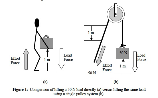
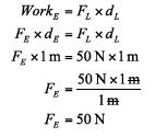
Notice that the distance over which the effort force is applied is the same in Figures 1a and 1b as the distance over which the load moves. Applying the equation for work allows us to see that the worker will need to exert 50 N of effort force whether he performs a deadlift or uses a pulley:
If the worker uses a single pulley system, he will still apply the effort force over a distance of 1 meter and exert 50 N of force. He still performs 50 J of work, thus the amount of work he performs on the load does not change. However, he has performed the work by applying effort in the same direction as the force of gravity. Despite expending the same amount of effort, using the pulley made it seem to him as if the amount of work that he performed was less because he was working with gravity rather than against it.
If the construction worker truly wants to expend less effort while lifting the 50 N load, then he must find a way to apply the effort over a greater distance because he cannot change the amount of work he must do to move the load. Now he is faced with another issue. Simple machines can provide a mechanical advantage to the operator by providing a way to change the ratio of the load force to the effort force, or by changing the ratio of the effort distance to the load distance. Increasing these ratios increases mechanical advantage.
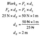
The amount of mechanical advantage provided by a machine is determined by its design. When the construction worker calculated the mechanical advantage for his single pulley system by dividing the load force by the effort force, he discovered that the single pulley system provided a mechanical advantage of 1. By using the equation for work and solving for the effort distance, he discovered that he can expend only 25 N of effort if he doubles the distance over which he applies the effort compared to the distance he must move the load:
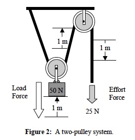
The worker needs a machine that can provide a mechanical advantage = 50 N/25 N, or 2. In a pulley system, each pulley provides a mechanical advantage of 1. To achieve a mechanical advantage of 2 the construction worker must add a second pulley to his system. Adding the second pulley increases the distance over which the effort force is applied because each segment of rope must move the same distance as the load moves as shown in Figure 2 below. The distance over which the effort is applied is the sum of the distance each segment of rope between the load force and the effort force moves.
Alternatively, the distance over which the effort is applied is the product of the number of pulleys times the distance over which the load is lifted. Therefore, the mechanical advantage in a pulley system is equal to the number of pulleys in the system.
As with pulley systems, levers also can be used to provide a mechanical advantage. The maximum mechanical advantage provided by a lever is determined by the placement of its fulcrum in relation to the load force and the effort force. The fulcrum of a lever is its point of rotation. The effort distance is the distance between the effort force and the fulcrum. Likewise, the load distance is the distance between the load and the fulcrum. There are three possible arrangements of the fulcrum, effort, and load, which commonly are referred to as classes (Figure 3).
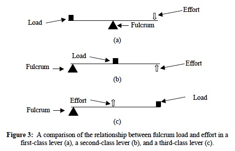
Figure 3a illustrates a first-class lever. In this arrangement, the fulcrum is located between the load and the effort. The effort and load forces in a first-class lever are both in the downward direction. Remember, mechanical advantage is the ratio of effort distance to load distance. Moving the fulcrum closer to the effort load decreases the effort distance (also called the effort arm length) and increases the load distance (also called the load arm length), thus decreasing the mechanical advantage. Moving the fulcrum closer to the load increases mechanical advantage by increasing the effort distance relative to the load distance.
In comparison, the fulcrums in second-and third-class levers are always fixed at one end of the lever while the positions of the load and effort change. In a second-class lever (Figure 3b), the load is between the effort and the fulcrum. For this reason, the effort distance will always be greater than the load distance, and the mechanical advantage will always be greater than 1. In contrast, the effort is located between the load and the fulcrum in a third-class lever (Figure 3c). Thus the effort distance will always be shorter than the load distance. As a result, the mechanical advantage in a third-class lever will always be less than 1. As a matter of interest, the major joints in the human body act as fulcrums for levers created by the adjoining bones. However, because the effort (represented by muscles) for each lever is located between the load and the fulcrum, the levers in the human body are all third-class levers. Thus they offer mechanical advantages of less than 1.
In this ELL, you will explore the concepts of work and mechanical advantage through experimentation with pulley systems and lever systems. You will examine how the design of each type of simple machine dictates its ability to provide mechanical advantage and discover that even though work seems easier when machines are used, the amount of work performed does not change.
CONTENT
- Fun Facts
- Learn the Lingo
- Get Focused
___________________________
FUN FACTS
Six Simple Machines
There are six commonly-encountered simple machines. These six simple machines: the pulley, lever, inclined plane, wheel and axle, wedge, and screw are each shown below with examples you will likely be familiar with.
The Pulley
Pulleys can offer no mechanical advantage as in the case with the weight machine on the left, to very large mechanical advantage as shown on the crane head in the middle. Perhaps nowhere has the application of pulley technology been so elaborately developed as in the rigging systems of the large sailing ship of history.

________________________
The Lever
Every lever has a fulcrum. As shown in the illustration below, the fulcrum is at the point where the bar makes contact with the small rock. As we go through the other examples of levers in this CELL, notice where the fulcrum is located. This can be tricky sometimes because a fulcrum is not always located in the middle of a lever, sometimes it is located at one end or the other.

________________________
The Inclined Plane
We see examples of inclined planes all around us every day. Notice that simple machines are often used in combinations to gain mechanical advantage and make work seem easier. For example, look at the deliveryman in the upper left of the illustration below. In addition to the inclined plane of the ramp, the hand-truck (or dolly) not only has wheels but also functions as a level when initially lifting the load (the boxes in this case.

________________________
The Wheel and Axal
In the case where effort or force is used to turn the wheel; the doorknob, sprinkler valve, screwdriver, and steering wheel in the examples shown below, notice that one complete turn of the wheel is always coupled to one complete turn of the axle. However, the distance that any point on the edge of the wheel (its circumference) travels can be much further than a point on the edge of the axle (its circumference). This is what provides the mechanical advantage when effort is applied to the wheel.

________________________
The Wedge
The important dimensions in terms of mechanical advantage with a wedge are its side length and its thickness. The side length is measured from the point of the wedge to the point where the tapering to the point begins. In the ship example below, the width would be from the point where the full width of the ship begins to taper to the bow.

________________________
The Screw
The illustration below shows a number of different ways in which screws are used. Often, we think of only the upper left and lower right examples of screws. You might be surprised at how many different devices contain the screw.

________________________
LEARN THE LABLEARNER LINGO
The following list includes Key Terms that are introduced within the Backgrounds of the CELL. These terms should be used, as appropriate, by teachers and students during everyday classroom discourse.
Note: Additional words may be bolded within the Background(s). These words are not Key Terms and are strictly emphasized for exposure at this time.
Investigation 1:
- Force: a push or pull on an object
- Load force: the weight of the object being moved
- Load distance: the segment of string or cord between the pulley and the load
- Effort force: the amount of force required to move a load
- Effort distance: the segment of string or cord between the effort and the pulley in a pulley system
- Work: a force applied over a distance. Work is calculated by multiplying force times distance.
- Joule (J): the unit used to measure energy and work. One joule is equal to one newton-meter.
- Mechanical advantage: a value that describes the relationship between a load force and the effort force needed to move the load. Mechanical advantage can be calculated either as the ratio of load force to effort force or the ratio of effort arm length to load arm length.
Investigation 2:
- Effort arm: the section of lever between the fulcrum and the effort in a lever system
- Load arm: the section of lever between the fulcrum and the load in a lever system
Investigation 3:
- There are no new Key Terms introduced in Investigation 3.
GET FOCUSED
The Focus Questions in each Investigation are designed to help teachers and students focus on the important concepts. By the end of the CELL, students should be able to answer the following questions:
Investigation 1:
- How can simple machines change the force needed to lift a load? Simple machines can change the force needed to lift a load by offering a mechanical advantage.
- How does mechanical advantage relate to effort and load forces? Mechanical advantage is the ratio of load force to effort force. If the load force is much greater than the effort force, then there will be a mechanical advantage.
Investigation 2:
- How can simple machines change the force needed to lift a load? In a first and second class lever, as the length of the effort arm or load arm is changed, the distance over which the effort must be applied or the load must be lifted changes. Because the distance over which these forces are applied changes, the effort force also changes.
- How does the relationship between the fulcrum, effort and load affect the force needed to lift a load? Changing the position of the fulcrum, effort, and load in relation to one another changes the distance over which a load is lifted and effort is applied. The result is a change in the effort force depending upon the lengths of the effort and load arms and position of the fulcrum, load and effort.
- How does mechanical advantage relate to effort and load forces and the lengths of effort and load arms? Mechanical advantage is equal to 1 when the load and effort force are equal and the length of the load arm and effort arm are equal. As the effort force decreases below that of the load force, mechanical advantage becomes greater than 1. As the effort force increases above that of the load force, mechanical advantage becomes less than 1. As the effort arm becomes longer than then the load arm, mechanical advantage becomes greater than 1. As the effort arm becomes shorter than the load arm, mechanical advantage becomes less than 1.
Investigation 3:
- How can simple machines change the force needed to lift a load? In a third-class lever, as the length of the effort arm is changed, the distance over which the effort must be applied also changes. Because the distance over which this force is applied changes, the effort force also changes.
- How does the relationship between the fulcrum, effort, and load effect the force needed to lift a load? Changing the position of the fulcrum, effort, and load in relation to one another changes the distance over which a load is lifted and effort is applied. The result is a change in the effort force depending upon the lengths of the effort and load arms and position of the fulcrum, load, and effort.
- How does mechanical advantage relate to effort and load forces and the lengths of effort and load arms? Mechanical advantage is equal to 1 when the load and effort force are equal and the length of the load arm and effort arm are equal. As the effort force decreases below that of the load force, mechanical advantage becomes greater than 1. As the effort force increases above that of the load force, mechanical advantage becomes less than 1. As the effort arm becomes longer than then the load arm, mechanical advantage becomes greater than 1. As the effort arm becomes shorter than the load arm, mechanical advantage becomes less than 1.
Note: These are succinct responses to the Focus Questions and are placed here for easy reference. Fully developed responses to the Focus Questions can be found on each PostLab page.
Note: Some questions may be revisited as the CELL progresses. As students acquire additional knowledge, their responses should reflect this.